Dr Ali Mohammed (Wagners CFT), Daniel Allen (Wagners CFT), Michael Kemp (Wagners CFT), Tim Payne (Enviroedge Group), Chris Goddard (Townsville City Council).
Abstract:
The vast majority of engineering projects are accompanied by different types of challenges which could be in the design, construction and/or operational phases. Geotechnical challenges are generally associated with the design and construction stage as it could involve designing the structure in a specific manner to suit an existing site condition or remedy the soil/ground strata. This paper discusses the geotechnical challenges of constructing access structure, Castle Hills Stairs in Townsville, and how it was overcome by adopting practical approaches and using innovative FRP materials.
Castle Hill stairs was to be built on a cliff face with a spherically weathered surface characterized by the formation of layers and wedges of weathered material on competent basalt rock. Hence, scaling work was to be undertaken to remove slope stability hazards i.e. detached and weathered flakes and wedges, which resulted in removing 150m3 of or rock surface. Then, the footing layout was set to match the proper anchorage points which involved drilling into rock and hydraulic pullout tests.
The structure was designed to suit the as-constructed slope face geometry and to meet the regulatory and structural requirements of walking track design as per AS2156.1 and AS1170. Designing the structure using FRP composite material was the key success of this project, mainly because of its high strength-to-weight ratio which allowed for effective utilization and rapid installation of long structural PFRP members. The successful completion of this project provided a centralised entry point from the heart of the Townsville city to Castle Hill for the local community and the city visitors to explore the beautiful walking tracks.
Introduction:
The construction industry is full of challenges where mostly every project has its is unique engineering approaches to meet specific site and design requirements. Many of these challenges are associated with the weight of construction material/components which are heavy and bulky to handle and transport especially in remote locating or sites with limited access.
The utilization of glass fibre reinforced polymer (GFRP) materials have significantly increased in the last couple decade as innovative/highly engineered material in the civil infrastructure. It become very popular and versatile due to its superior characteristics compared to traditional building materials i.e. concrete, steel and timber. The favourable properties of GFRP materials such as high strength, lightweight and corrosion resistance, have made it the material choice for structures in aggressive environments or those with limited site access (Vedernikov et al., 2020). One of the most adopted FRP manufacturing methods is the pultrusion process where the glass fibres are being pulled through a heated die whilst it is being impregnated with a specific resin mix through injection as depicted in Figure 1 (Advani and Hsiao, 2012).
A good example of utilising these novel section is Castle Hill Stairs Project in Townsville, Queensland where an innovative FRP structure was designed and constructed using pultruded FRP material to connect Townsville City with Castle Hill. Townsville City Council (TCC) secured funding from the Commonwealth Government in 2019 for the design and delivery of “The Castle Hill Experience”. This initiative provided a $1.965M injection of funds under agreement under the “Building Better Regions Fund” to develop Castle Hill experiences, The Castle Hill Connection formed part of that agreement. As part of the agreement TCC matched that figure $ for $.
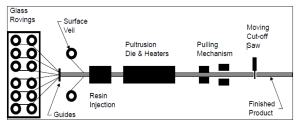
Figure 1 – Schematic diagram of the pultrusion process.
Castle Hill stairs project
At approximately 14 metres short of a mountain, Castle Hill is the giant granite monolith that stands proud in the centre of Townsville – a perfect place for visitors to orientate themselves. Castle Hill has several popular walking tracks and trails, which are frequented by more than 2,500 locals a day.
Castle hill has always lacked an access directly to the beating heart of Townsville city. Townsville City council evidently realized the potential of this and created a project to undertake an elevated staircase ascending the walker street face of castle hill. The Walker St connection to deliver a new point of transit access to the Castle Hill Summit.
Initial designs were completed for Townsville City Council by LCJ and Golder, providing a basis of foundation protocol for the foundation design.
Site challenges and adopted solutions
In conjunction with delivering an exciting new Transit to Castle hill, an obligation to reduce the current Hazard status at the location to a safe low or very low criteria was required. The geotechnical hazards already present were assessed and compared to initial geotechnical remediation advice (Parisi, 2020). The process for rectifying the exhibited hazards was a relatively straightforward and practical approach. By utilizing winch assisted spider excavators with rock hammer attachments along with a 35t excavator to scale the cliff face back removing all Hazards on the lower stair site and upper cliff faces thus providing a geometrically satisfactory slope and ideal foundation locations for the staircase footings (Figure 2).
Foundation design involved concrete footings keyed into rock and pinned with rock anchors and reinforcement dowels was completed by Wagners Sub-consultants Icubed and Golder completing geotechnical engineering. Initially hand calculations, due to inherent complexly of semi vertical foundations pinned with rock anchors, FEA modelling was incorporated by Icubed to assess possible gapping and detail an understanding of the mechanical stresses.
In the course of the final survey foundation set out, further assessment of the rock face by Golder identified a large wedge mass of granite at the proposed location of the intermediate landing. A detailed inspection of the potential Hazard was carried out from an elevated working platform to closely inspect the hazard and obtain measurement of key geotechnical features. NH10 consisted of a large granite block, secondary weathered/residual granitic mass retained upslope and resting on a basal plane steeply dipping outward toward Walker Street. Based on outcomes of detailed inspection and subsequent stability analysis provided by Golder, NH10 – as it was then referred – was presented as a “High” geotechnical risk to our proposed structure and directly below to influence zone.
Geotechnical stabilization design work started immediately on NH10, in an effort of keeping the current foundation setout noted as key to utilizing already completing foundations and keeping to the programmed completion date. The first option, Pinning the NH10 rock back to cliff face proved to be especially complex, with the amount of pinning in conjunction with pins already required by foundations proved to be congested and a large risk for site works. The second design option – a rock anchored buttress wall at a lower area of the hazard avoiding the congestion involved in the first option and allowed pinning for foundations to occur, but unfortunately not cost-effective. The third option was to bridge the rock and remove the foundation from the rock entirely. This was only a possibility due the increased strength to weight ratio of the Wagner composite pultruded FRP sections.
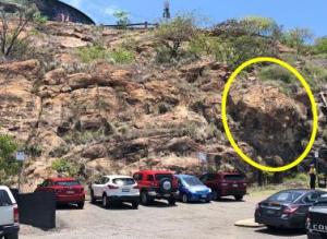
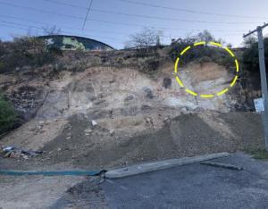
Figure 2 – Hazard remediation
On site anchor pull-out testing
On-site actual pull-out test was undertaken to assess the actual bond strength of anchored embedded/grouted in the ground as shown in Figure 3. A sacrificial test dowel was used for the test using 28mm diameter, Grade 500N threaded bar grouted in 75mm diameter drilled hole. The hole was 1m deep, with a bond/grouted length of 0.68m. A grout is of 20MPa compressive strength at 2 days was used to fill the drill hole by gravity after the hole was cleaned by compressed air.
The target test load was 160kN, while the maximum safe test load is ~245kN which is based on 80% of the anchor’s ultimate tensile strength. The test load was increased incrementally at 20% intervals up to 80% of the safe load. The applied was held for 5min, or until stabilization. The deflection at each step was measured at time intervals of 0, 30s, 60s, 1min, 2min, 3min and 5min. The point of failure is defined as either if total deflection exceeded 0.1% of the dowel bond length, or if creep deflection exceeded 2mm per log time.
The test load reached 1.5 times the target test load without any sign of failure. Then the test was terminated due to reaching the safe load mark.
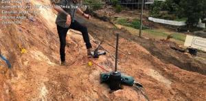
Figure 3 – On-site anchor pull-out test
Installation of Castle Hill stairs
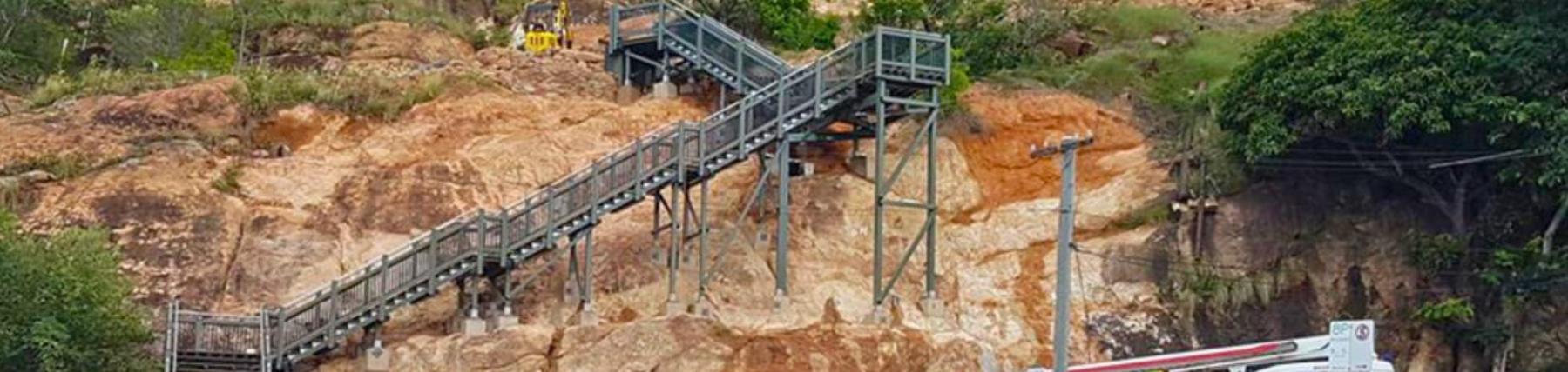
Installation was completed with Local major Subcontractor Enviroedge employed for their specialized equipment and personnel as pictured in Figure 4.
Major excavation work and drilling of the rock anchors were undertaken by a variety of machinery, including an Atlas Copco mobile rig, Euromach MM2500, Menzi Muck A20 spider excavator and Atlas Copco mast along with atlas Copco hammer for scaling works. The spider excavators were vital to drilling and removing hazards above the reach of the 35t excavator used from the lower ledge. 32mm DSI micro piles and Ischebeck titan 30 /11 micro piles were installed ranging from 1.5 to 2m embedment depths. The micro piles were assembled with tremie line and centralizers to the required lengths on-site and then installed and grouted in place.
Additional Rope access abseil drilling and scaling of geotechnical hazards were undertaken at the top of the structure exit. Chemical splitting of sections of the rock face was required to split and remove segments of rock that were positioned in the way of the structure footprint.
The structure assembly was completed with various machineries such as Spider excavators, EWP and crane works. Due to close proximity to power lines, the machinery had to remain compact which restricted many aspects of access, however, due to the lightweight of the FRP members, the installation with small machinery and also by hand, proved to be efficient and safe construction methodology.
The lightweight materials were drilled, inserted and pre-assembled on-site using detailed shop drawings, moved into place with a crane and installed from ropes and EWP.
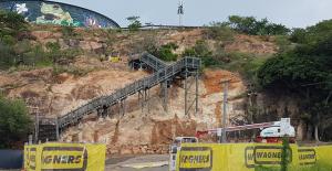
Figure 4 – Installed Castle Hill stairs
Conclusions
This discussed the challenges of Castle Hill Stairs project in Townsville, QLD where several geotechnical challenges were overcome with practical approaches and utilising innovative and light-weight yet strong pultruded FRP sections.
The light-weight of the FRP section used in the project helped a lot in the construction of the project where the site has limited access due to its location over a steep cliff. The successful completion of this project provided a vital link between Castle Hill and Townsville city where the local community have greatly benefited from.
Acknowledgement
The authors acknowledge icubed consulting, Enviroedge Group, Golder and Townsville City Council for their contribution to Castle Hill stairs project.
References
ADVANI, S. & HSIAO, K.-T. 2012. Introduction to composites and manufacturing processes. Manufacturing Techniques for Polymer Matrix Composites (PMCs). Elsevier.
PARISI 2020. Castle Hill Walker Street Connection Project.
VEDERNIKOV, A., SAFONOV, A., TUCCI, F., CARLONE, P. & AKHATOV, I. 2020. Pultruded materials and structures: A review. Journal of Composite Materials, 54, 4081-4117.