Ali Mohammed, Lead Structural Engineer, Wagners CFT; Lachlan Nicol, Engineering Manager, Wagners CFT; Michael Kemp, Executive General Manager, Wagners CFT; Rohan McElroy, Principal Structural Engineer, icubed consulting.
ABSTRACT:
This paper will discuss the design of a 30m pedestrian bridge that was installed over Mersey River in Kejimkujik National Park, Nova Scotia, Canada, including the basis for the selection of the key structural material, Fibre Reinforced Polymer (FRP). FRP material is an engineered product, its mechanical properties can vary significantly from one manufacturer to another mainly depending on the manufacturing methods and the raw material used in the process. These mechanical properties are part of the design process as key inputs for Finite Element Model (FEM) to simulate and analyse the bridge performance under all load cases i.e. dead, live, wind, snow, water, seismic, etc.
This paper will also focus on the dynamic performance of the bridge, and the design and experimental testing/validation of the utilised chord splices which were required due to the bridge sections being manufactured in Australia, shipped to Canada and spliced/installed on site. Finally, it will highlight the key quality benefits of selecting a FRP composite bridge over traditional materials for the Mersey River pedestrian bridge.
1 INTRODUCTION:
The utilisation of glass fibre reinforced polymer (FRP) materials has significantly increased in the last two decade as innovative/highly engineered material in the civil infrastructure. It has become very popular due to its versatility and its superior characteristics compared to traditional building materials i.e. concrete, steel and timber. The favourable properties of GFRP materials such as high strength-to-weight ratio, durability, corrosion resistance, have made it the material choice for structures in aggressive environments or those with limited site access (Vedernikov et al., 2020, Mohammed et al., 2020). FRP structural sections can be manufactured using various methods i.e. pultrusion process, filament winding, hand layup, moulding, vacuum infusion, etc. The pultrusion method is arguably the most widely used method in FRP manufacturing for civil and structural applications as it is continuous and very cost-efficient process. It is depicted in Figure 1 where the glass rovings are being pulled through a heated die over a mandrel whilst it is being impregnated with a specific resin mix through injection points (Advani and Hsiao, 2012).
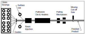
Figure 1. Schematic diagram of the pultrusion process
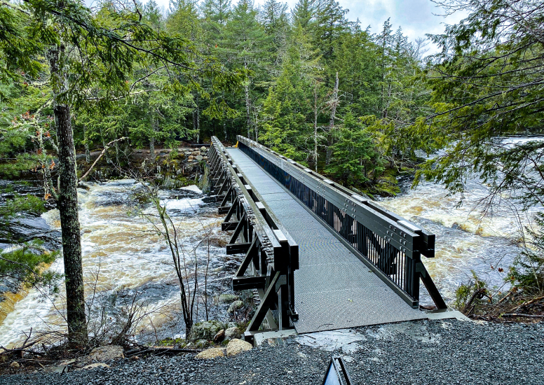
A good case study of utilising pultruded FRP material in structural applications is the Mersey River Bridge in Canada (Figure 2). The Mersey River Bridge is an innovative and sustainable infrastructure development aimed at replacing an old bridge that was destroyed by Hurricane Dorian in 2019. The project is located in Kejimkujik National Park, Nova Scotia, Canada, and was commissioned and installed by Parks Canada, in collaboration with the several other entities. The primary objective of the project was to design and construct a lightweight, durable, and corrosion-resistant bridge that could withstand the harsh environmental conditions of the park, including frequent flooding, high winds, and extreme temperatures. The project also aimed to reduce the environmental impact of bridge construction and maintenance by using sustainable and durable materials. The carbon footprint assessment model developed by Hu and Yang (2012) showed that carbon emissions can be reduced by 40% by utilising FRP material instead of steel for civil structures. Hence, FRP composites was the material of choice for the Mersey River Bridge considering its sustainability, durability (100-year design life) and its high strength-to-weight ratio which was a key for ease of the innovative installation method. The bridge was designed/built in truss style to span 30m over Mersey river and links to a recently developed trail (Ukme’k Trail) within the national park.
Figure 2. Mersey River FRP Footbridge, Kejimkujik National Park, Nova Scotia, Canada.
2 DESIGN WORK
2.1 OVERVIEW AND LOADING
The design criteria for Mersey River Footbridge from the client included multiple design codes and specifications that were required to be designed to. A summary of these can be found below:
- Canadian Bridge Design Code (CAN/CSA S6-19)
- Parks Canada Mersey River / Harbourside Specification
- American Society of Civil Engineers – ASCE 7
The load combinations for Canadian Standards are not too dissimilar to those seen in Australia and New Zealand. Generally for ultimate loads, the dead loads were factored up by 1.1 to 1.2, live loads were factored up by 1.7, snow and ice accretion loads were factored up by 1.3, and water forces by 1.3 as per the standards mentioned above.
A brief summary and comments on the proposed loading on the bridge can be found below:
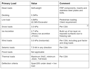
Table 1 – Primary load case summary
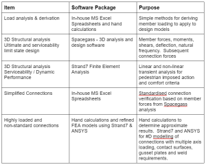
Table 2 – Software package summary
2.2 TRUSS GEOMETRY AND FINAL SOLUTION
During the preliminary design phase of the footbridge, multiple design iterations were required to inform the form and function of the FRP trusses. The style of trussed bridge described above is called a ‘pony’ truss, given its name because it allowed for ponies or horses to cross the structure without hitting any supporting structural members in the late 19th century.
The geometric and member sizing of the outside edge trusses is vitally important to ensure the structure is stiff and strong enough to withstand the imposed loading while spanning the 30m to abutments. Using in-house spreadsheets, icubed the lead design engineers, were able to quickly iterate truss options by manipulating the truss chord vertical spacing and trialing multiple Wagners CFT profiles. The theory used to iterate this solution was the Parallel Axis Theorem by Jean Baptiste Joseph Fourier, derived back in 1822. Once a suitable truss solution was found, time was spent adjusting the Spacegass 3D models to suit the ideal truss solution and verifying the results with spreadsheets and hand calculations.
Originally, the design started with truss chords positioned high above the deck level to avoid the lower soffit encroaching on the 1:100 year flood height for the stream below the bridge while using as efficient member as possible. As the design was iterated, it became apparent that compression chord buckling would be one of the governing failure criteria along with the clients’ aesthetic requests. For aesthetics, the client wished for the upper truss chord to be below eye level as pedestrians were traversing the structure to ensure that while crossing the bridge, the user was able to fully appreciate the surrounding environment. To achieve this requirement, part of the bridge bottom chord structure was dropped below deck level, and the chord members were increased in size to achieve additional stiffness in order to span the 30m.
This presented some difficulties in that to achieve the aesthetic requirements, the shallower truss chord vertical spacing increased the axial loads in the chords, decreased the overall bridge stiffness but also increased the buckling resistance of the top chord. This creates a bit of a ‘dance’ between fighting with larger chord forces to be transferred to connections, trying to balance minimum deflection requirements and cross-checking top-chord member buckling performance to ensure a buckling failure mode was not present. The final bridge design produced a deflection ratio for dead plus live load of Span / 320, which was less than the design requirement of Span / 250.
2.3 DYNAMIC PERFORMANCE
2.3.1 PEDESTRIAN COMFORT
Verification checks on pedestrian induced excitation performance due to the lightweight nature of FRP structures were undertaken. The methods used assess bridge deck accelerations in accordance with international research and have backed this up with in-situ testing of existing FRP bridges.
The detailed assessment of pedestrian comfort criteria was undertaken as per the study published by McElroy (2022). The assessment consisted of modelling a pulsating force load produced using Fourier Transformation equations to replicate the vertical and horizontal impact of a footfall load. This load was applied to the deck in a 3D model and factored using formula to evaluate the effect of multiple pedestrians walking in-sync and out-of-sync across the structure. A transient solver produced graphs of maximum nodal accelerations under various pedestrian cases which were then compared to acceleration limitations outlined in other literature.
Generally, the bridge structure did not show deck accelerations in excess of the perceived limit except for a slow walking, syncronised footfall event, such as those from a marching band.
2.3.2 AEROELASTIC INSTABILITY
During the detailed design of the bridge structure, the aeroelastic instability was verified against CSA design code. Aeroelastic instability occurs when the motion of the structure in wind produces aerodynamic forces magnifying the same motion. Mersey River bridge is not subject to wind speeds capable of producing aerodynamic instabilities.
icubed also undertook an independent review of aerodynamic performance to British Standards Bridge Design part 49/01 whereby checks were completed against vortex excitation, limited amplitude response / turbulence and classical flutter.
2.4 CONNECTIONS
2.4.1 CRITICAL CONNECTIONS
Due to the wind, seismic, ice and live loading required on Mersey River Footbridge, there were a number of critical truss connections that were highly loaded. These connections included:
- End chord to verticals
- End diagonals to chords
- End verticals to the abutment
- Horizontal subfloor bracing
2.4.2 SPLICE CONNECTION
Due to transportation requirements for 40ft containerised cargo for the bridge structure from Australia to Canada, a splice connection design was required to connect the bridge chords to one another in-situ, effectively joining two bridges to create one long span.
The main issue with splice connections (Figure 3) for bridge chords is they are required to carry the full axial, shear and bending load requirements across the broken joint from one chord to the next. Within this vicinity, a number of items are required to be checked such as ultimate strength performance of the splice, serviceability performance of the splice and fatigue performance.
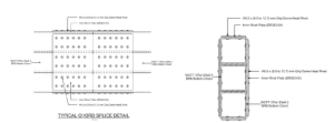
Figure 3. Details of the splice connection.
The design of the splice connection riveted group was undertaken using an in-house spreadsheet for the assessment of a bolt patterns ability to resist torsional moments perpendicular to the plate by using the polar moment of inertia of the group. This is represented by the below figure.
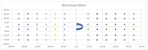
Figure 4. Splice connection design for the rivet (bolt) group – incorporating polar moment of inertia.
From here, the forces and moments were broken down into maximum resultant and component shears to check against shear capacities and bearing strengths. The detailed design analysis, subsequent preparation of load testing and analysis of testing results of the compression chord splice plate were based upon manual hand calculations for plate buckling and further verified using a study that us published by Kelpša and Peltonen (2019). The theory presented in this paper were coded into a spreadsheet and used to verify different plate geometries under multiple loading criteria.
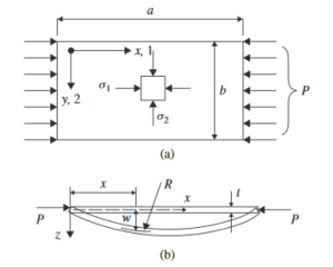
Figure 5. Buckling of a wide plate strut by Kelpsa and Peltonen (2019).
2.4.3 SUBFLOOR STRUT CONNECTION
Finite element modelling was undertaken to refine the gusseted plated connection required on the horizontal sub-structure brace due to lateral wind loading actions. The FEA model in Ansys allowed the designers to investigate areas of peak imposed stress in the stainless steel material and to compare these against yield stress limits. Further to this, more accurate combined bolt actions in tension and shear were extracted to refine the bolted connection design.
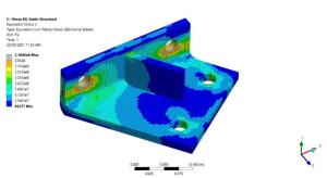
Figure 6. FEA bracket connection in ANSYS
2.4.4 ABUTMENT END SPAN CONNECTION
In a similar fashion to the lateral brace connection above, a finite element model was also undertaken to refine the gusseted plated connection required on the abutments to connect the bridge chords to the reinforced concrete elements. The loading that governed this connection design varied from wind actions for shear (transverse load on connection), to thermal and live loading sliding connection design. Uplift was governed by combined transverse and uplift wind conditions.
The FEA model in Strand7 allowed the investigation of areas of peak imposed stress in the stainless steel material and to compare these against yield stress limits. Further to this, more accurate combined bolt actions in tension and shear were extracted to refine the bolted connection design.
3. EXPERIMENTAL VERIFICATION OF THE SPLICED CONNECTION
All the physical, mechanical and chemical properties of the FRP composites were already characterised and published by Wagners CFT (2021). However, since the bridge components were manufactured in Australia and to be shipped to Canada in standard 40ft shipping containers as mentioned previously. The truss bridge was designed to be spliced at the top and bottom chords using 5mm stainless steel plate (Grade 316) and 6.4mm structural rivets as shown in Figure 3. Considering the nature and the importance of this splice connection, A prototype of the spliced connection was fabricated to be tested for the ultimate design axial forces that were to be transferred through the truss chords and verifying the theoretical design.
3.1 TEST METHODOLOGY
The test sample and test setup are shown in Figure 7. The test sample was fabricated as a replica of one single side of the chords, with internal bonded anti-crush blocks at the top and bottom ends to avoid any local crushing. A 20mm gap allowance was made between the FRP sections for the purpose of testing only to simulate potential onsite tolerancing allowance where it must be assumed, As a worst case basis, that the full load was to be transferred through the splice itself with no bearing load between chords allowed for. The deformation was captured using a linear potentiometer, and the test load was applied using a hydraulic ram and 50t load cell, both the load and deformation were recorded using a DT80 Datataker.
The test load was adopted based on the consolidated ultimate design force obtained from the bridge structural analysis using SPACE GASS software (268kN). In addition, the ultimate design load was factored up considering a coefficient of variation of structural characteristics (Vsc) of 1.256 for 6% variation on the prototype testing as per AS/NZS1170.0. The Ultimate Limit State load (ULS) for testing purposes was therefore determined to be 336 kN. The test procedure was then carried out following the below loading steps:
- Preload to 50% of ULS load (168 kN), return to zero load and measure the gap distance
- Apply and hold ULS load (336 kN) for 15 minutes, and return to zero
- Load until failure
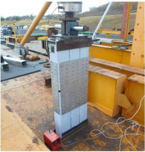
Figure 7. Experimental compressive test setup of the spliced connections
3.2 TEST RESULTS AND OBSERVATION
The splice prototype was tested/loaded to 50% of ultimate limit state, 100% ultimate limit state, and then to final failure. The sample successfully withstood the ultimate test load for 15 minutes as shown in Figure 8. After that, the sample was loaded until it failed ultimately at 520kN where the steel plates buckled at the mid-height as expected (Figure 9). It is noteworthy to highlight that that there was no failure in the FRP components, and higher spliced connection capacity can be achieved by using thicker plates. The test results verified the theoretical design and provided confidence in the proposed connection to be used in Mersey River truss bridge.
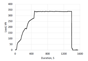
Figure 8. Ultimate test load vs duration curve.
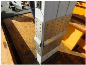
Figure 9. Failure mode of the tested sample.
4. INSTALLATION
The transport and installation of the Mersey River bridge in Canada was another remarkable feat of engineering. The 30m long FRP truss bridge members were manufactured in Australia, shipped to Canada in standard 40ft shipping containers and assembled on site into small bridge sections as shown in Figure 10a. Considering the nature of the project location and due to its limited access, an innovative and practical installation methods had to be adopted.
The installation process was carried out with great care and precision, involving the use of cranes and specialised equipment to lift and position the bridge segments. Ziplines were also installed across the river to carry the bridge sections into place. The lightweight nature of the FRP materials was a key element that was considered in the feasibility of the proposed bridge. Scaffolding was installed across the river in the dry season when the water levels were low, Figure 10b. The final assembly and fastening of the bridge was also carefully monitored and tested to ensure it met the required safety standards.
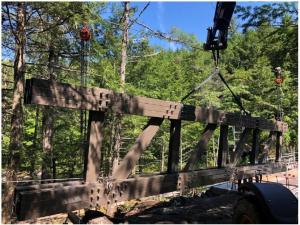
a) Bridge segment placed into position using zipline.
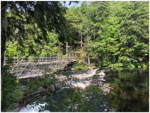
b) Bridge segments are assembled together
Figure 10. Assembled bridge sections being installed on site.
5. CONCLUSION
This paper discussed the design and installation of Mersey River Bridge in Kejimkujik National Park, Canada. It also presented the basis for the selection of FRP composites and highlighted the material performance in experimental tests. The successful design and installation of 30m FRP truss bridge is an excellent example of innovative and sustainable infrastructure development that demonstrates the potential of FRP composites in bridge applications. It now stands as a testament to the innovation and expertise of FRP structural design, manufacturing and construction.
6. REFERENCES
ADVANI, S. & HSIAO, K.-T. 2012. Introduction to composites and manufacturing processes. Manufacturing Techniques for Polymer Matrix Composites (PMCs). Elsevier.
HU, A. H. & YANG, S. Y. Green Materials? Carbon Footprints Comparison of Steel and FRP Structures. Proceedings of the 2012 Second International Conference on Electric Technology and Civil Engineering, 2012. 1445-1448.
KELPŠA, Š. & PELTONEN, S. 2019. Local buckling coefficient calculation method of thin plates with round holes. ce/papers, 3, 841-846.
MCELROY, R. 2022. A serviceability analysis of pedestrian induced excitation of light-weight FRP footbridges.
MOHAMMED, A. A., MANALO, A. C., FERDOUS, W., ZHUGE, Y., VIJAY, P., ALKINANI, A. Q. & FAM, A. 2020. State-of-the-art of prefabricated FRP composite jackets for structural repair. Engineering Science and Technology, an International Journal, 23, 1244-1258.
VEDERNIKOV, A., SAFONOV, A., TUCCI, F., CARLONE, P. & AKHATOV, I. 2020. Pultruded materials and structures: A review. Journal of Composite Materials, 54, 4081-4117.
WAGNERS CFT 2021. Design Guide. 04 ed.: Wagners.
ACKNOWLEDGEMENTS
The authors acknowledge the efforts of Parks Canada, the installation team and all the parties and personnel involved in the successful completion of this project.
