Dr Ali Mohammed (Wagners CFT), Lachlan Nicol (Wagners CFT), Michael Kemp (Wagners CFT) and Bjorn Jachmann (Kehoe Myers).
Abstract:
The utilization of Pultruded Fibre Reinforced Polymer (PFRP) materials in civil/infrastructure applications is increasing rapidly given their superior characteristics such as high strength, lightweight, excellent durability, corrosion resistance, ease of transportation, speed of assembly, and nonmagnetic/nonconductive nature. Light poles are one of the most promising applications for pultruded FRP composite products instead of traditional light poles as it provides a sustainable solution for the frequent replacement of the existing ones due to aging and degradation. This paper discusses the manufacturing, testing, design, transportation and installation stages of PFRP light poles. The basics of the pultrusion process are presented in the light poles manufacturing stage where the novel parameters and state-of-the-art pultrusion techniques are highlighted. Full-scale experimental tests were undertaken to evaluate the structural integrity of the pultruded FRP poles. This was followed by a numerical model that has been developed based on the experimental results for further analysis. Also, the design procedure and the inherent properties of FRP composite materials i.e. strength and stiffness, of FRP light poles are discussed in the design stage. Moreover, the ease of transportation and installation of the lightweight FRP poles is also highlighted where they can be direct buried or fixed using bonded or bolted anchor base. The anchor base can be fabricated to suits any existing rag bolts layout which provides an excellent option for direct replacement of aged/degraded light poles. Finally, a case study of actual projects where PFRP poles have been installed is presented highlighting their excellent performance during the serviceable life.
Introduction:
Fibre Reinforced Polymer (FRP) composite materials are being used increasingly in various applications in the area of Civil Engineering as new infrastructure and/or replacing the existing ones. The reason behind the increased utilisation of FRP composites is their superior characteristics compared to traditional materials in terms of strength-to-weight ratio, non-corrosive nature, durability, and low life-cycle maintenance (Sakr et al., 2005). A good example of that is the trend of using of FRP light poles in lieu of the commercially available metallic ones such as steel/aluminium (Salib and Abdel-Sayed, 2012). FRP light poles are generally manufactured with two main methods i.e. pultrusion process and filament winding. The pultrusion process is a continuous and highly efficient manufacturing method of FRP sections where the fibres are mainly oriented in the longitudinal direction along the pulling line. The filament winding method, on the other hand, the section manufacturing involves a rotating mandrel and a carriage travels horizontally along the length of the mandrel winding the filaments around. It is a less automated process than pultrusion and the fibres are mainly oriented along the circumference of the section (Advani and Hsiao, 2012).
Higher fibre volume fraction (> 60% by volume) is more achievable in the pultrusion process compared to filament winding and other FRP composites manufacturing methods. Hence, high mechanical properties are usually associated with pultruded sections. Moreover, the pultruded FRP (PFRP) sections have higher characteristic mechanical values in the longitudinal direction than the transverse direction. In contrast, the filament wound sections have better properties in the hoop direction given the orientation of fibres. Therefore, the PFRP sections are generally utilised for compression, tension and flexural applications as columns, truss members, joists, piles, poles, etc. Whereas filament wound sections are more efficient for confinement applications and/or closed-end structures i.e. pressure vessels. Nevertheless, PFRP members still can be manufactured with sufficiently high transverse properties through pull winding technique or using mats (unfavourable) to provide off-axis fibres. Having off-axis fibres help the pultruded members to better manage the multiaxial stresses and extend their range of applications, coal seam gas pipes for example. Similarly, filament wound sections can also be made with a steep angle and sufficiently large profile to meet the strength/deflection requirement of pole applications, but that comes at the cost of extra raw materials used in the section.
This paper discusses and describes the main parameters of the various stages of PFRP light poles i.e. manufacturing, testing, design transportation and installation. The PFRP light poles of this study are manufactured by Wagners Composite Fibre Technologies (WCFT) by pultrusion process with a unique pull winding process.
Light Poles Manufacturing:
The PFRP poles of this study are manufactured locally the by pultrusion process where the glass fibres are being pulled through a heated die whilst it is being impregnated with a specific resin mix through injection as depicted in Figure 1. The wetted-out material is pulled over a heated stainless steel mandrel that ensures it holds its shape during the curing process. The heaters that are located in the die initiate the exothermic reaction to cure the resin and solidify raw material into one integral profile. An automatic cutting saw is located at the end of the pultrusion line programmed to cut the finished products at pre-defined lengths.
Unique pull winders are integrated with the pultrusion line allowing novel fibre layup which involves several layers of unidirectional fibres (UD) and wound fibres (WD). The UD/WD ratio and the off-axis angle of the wound fibres are predetermined based on the desired mechanical properties of the final product, i.e. whether higher strength is required in the longitudinal direction or along the transverse/hoop direction. Therefore, the developed PFRP poles are manufactured with UD/WD ratio of 80/20 with a WD angle of 50° off the longitudinal axis achieving high longitudinal strength and stiffness to meet the design/deflection requirements and sufficiently high transverse strength to manage the multi-axial stresses.
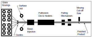
Figure 1 – Schematic diagram of the pultrusion process.
Large scale flexural tests of PFRP Light Poles:
A series of small scale and large-scale testings were undertaken on the PFRP light poles to characterise their physical and mechanical properties and evaluate the performance of large-scale sections. This paper focuses on the full-scale testing part, while the physical and mechanical properties are reported in (Wagners CFT, 2016).
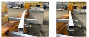
Large scale samples of 100x100x5.2 square hollow section (100SHS) and 125x125x6.4 structural hollow section (125SHS) with bonded (Figure 2) and bolted (Figure 3) steel brackets were prepared for this test. The test aims to evaluate the overall performance of the PFRP poles and prove the structural integrity of the bonded base as it is a preferable option for aesthetic reasons. The steel bracket has a 16 mm thick base and 348 mm long spigot for the 100SHS profile, and a 20 mm thick base and 504 mm long spigot for the 125SHS profile. A two-part glue was used for bonding the light pole and the steel base through three 6mm injection holes onto two opposite faces of the pole.
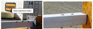
Figure 2 – Glued Base Figure 3 – Bolted Base
The length of the 100SHS profile was 3000 mm and the load was applied at 200 mm away from the top resulting in a 2800 mm lever arm, whereas the 125×125 composite pole, the profile length was 4700 mm. The load was also applied at 200 mm away from the tip creating 4500 mm lever arm. Anti-crush inserts were used at the loading points to avoid local/premature failure. The tested samples were loaded monotonically using 0.75t mechanical rachet and 1t load cell.
Table 1 presents a summary of the flexural test results, while Figure 4 shows the moment-duration curve of the 100SHSand 125SHS composite poles. Firstly, the 100SHS pole was loaded up to 4.11 kN (2.8 lever arm) resulting in a bending moment of 11.5 kN.m at the base. This moment magnitude is equivalent to the highest design moment capacity of 100SHS poles at wind region C. The sample successfully withheld the applied load for 2 minutes. Then, the moment was increased to 13.8 kN.m considering a kt factor of 1.2 as per (AS/NZS 1170, 2002). The tested sample successfully withstood the applied moment with a hold duration of 2 minutes. After that, the specimen was loaded up to failure which occurred at a moment of 19.3 kN.m. The failure was localised at the interface between the steel base and steel spigot of the steel bracket as shown in Figure 5, with no signs of failure in the pole nor the glued connection.
Regarding the 125SHS pole, it was loaded to its design moment capacity, 18.7 kN.m (4.16kN x 4.5m) and beyond, by considering a kt factor of 1.2 as detailed in Table 1. In both scenarios, the tested sample withheld the applied load for 2 minutes. After that, the sample was loaded up to failure (25.9 kN.m) where it failed in a similar manner to that of 100SHS with the spigot being sheared off at the weld line with no signs of failure at the pole nor the pole-glued bracket interface. The experimental ultimate moment capacities aligned well with the structural analysis undertaken using SPACE GASS software as shown in Figure 6 and Figure 7 for 100SHS and 125SHS, respectively.
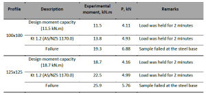
Table 1 – Summary of test results
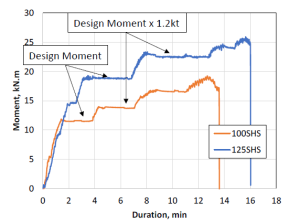
Figure 4 – Moment duration curve of the 100 SHS and 125 SHS
a) Loaded sample b) Sample at failure
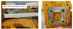
c) Steel bracket failure
Figure 5 – Failure mode of the tested samples
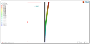
Figure 6 – SPACE GASS model of 100SHS
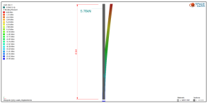
Figure 7 – SPACE GASS model of 125SHS
Structural design of PFRP Light Pole:
The structural design of the PFRP light poles is very similar to the design of steel light poles and the same principles can be applied. However, the main differences of these two materials are the E-Modular.
Material Properties for Steel – RHS Profiles:
E-Modular E = 200,000 N/mm2
Yield Strength fy = 350 N/mm2 or 450 N/mm2
Tensile Strength fu = 430 N/mm2 or 500 N/mm2
Material Properties for CFT:
Tensile E-Modular E = 36,300 N/mm2
Tensile Strength fcu = 610 N/mm2
Compressive E – Modular E = 33,300 N/mm2
Compressive Strength ftu = 485 N/mm2
The E- Modular of the used PFRP poles is only 1/6 of the E-Modular of the steel but with similar strength properties. That means the focus during the design will be the serviceability criteria such as deflection and dynamic behaviour.
Design Loads and Serviceability Criteria
Unsurprisingly the main design load for light poles is the Wind Load. Typically, the permanent loads of the light pole, the light and any solar panels can be neglected. However, the size of the light and solar panel can contribute significantly to the Wind Load.
Generally, light poles can be classified as an importance level 1. This means the basic ultimate design wind speed of v500 and serviceability wind speed of v25 can be used for the various wind regions.
The Australian standard does not specify specific serviceability criteria for light poles. The American Standard is recommending a maximum deflection under a serviceability wind load of h/7. Which equates to a deflection limit of 1,285mm for a 9,000mm height light pole. It sounds a lot, but the service design wind speed for wind gusset which is to the wind regions and locations and typically in the order of 121 to 165 km/h. Under this condition the public traffic is coming is on hold to stand under the flickering light will not affect public safety.
Dynamic Response
Another serviceability criterion is the wind-induced dynamic response of slender structures. There are two effects on how the structure will respond.
1. The light pole is responding perpendicular to the wind direction which is generally the most severe effect causing the most load cycles. These cycles are the main reason for fatigue and need to be investigated. Tall structures like industrial chimneys collapsed under this load.
2. The light will respond in wind direction which is known as galloping. Generally, this effect is neglected.
The focus will be the response perpendicular to the wind direction. This is subjected to the frequency of the structure and the material properties of the PFRP material especially the logarithmic decrement. The response of these light poles was assessed using the European Standard DIN EN 1991 – 1 -4: 2010 – 12. This standard is offering two methods to calculate the maximum amplitude and the number of load cycles during a design life of a structure.
Example of 9m height light pole
A 125SHS light pole with a height of up to 9m was designed and the below information was determined following a complex design process Equation 1.
The calculation provided for the following outcomes:
1. Frequency: f = 0.775 Hz
2. Logarithmic decrement (Tested by USQ) S = 0.0252 [1]
3. Critical Wind speed: v = 2.91 km/h
This is wind when the structure will have the maximum response perpendicular to the wind direction.
4. The maximum amplitude: y = 4.3mm
This amplitude occurs at the critical wind speed and equates to height to deflection ratio h/2,093.
5. The maximum moment due to dynamic response M = 51.3 Nm
6. The number of load cycles for 50 years design life: N = 6,000,000
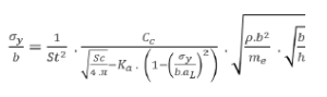
Equation 1
Despite the low frequency, the dynamic response will result in an amplitude of only 4.3mm and a maximum bending moment of only 51.3Nm. This will cause low-stress levels at the base of the light pole and minor flicker effects from the bouncing streetlight. However, the 6,000,000 load cycles will cause fatigue. Due to the low-stress level even under serviceability wind speed a 50-year design life for light poles can be considered safe.
Transport and Installation:
The light poles are wrapped with UV resistant special wrap protecting the products from external pollutants during transport and storage as shown in Figure 8. The transport of PFRP light poles is more efficient in terms of cost, fuel and transport size compared to the light pole made of traditional material given the lightweight of the former. Furthermore, adopting light-weight products makes the installation process highly efficient where a small or no mechanical lifting equipment would be required at the installation depends on the height of the pole. These light poles can be installed with direct burial or using anchored bases as sketched in Figure 9. For the direct burial installation method, an approved backfilling procedure has to be followed. While the anchored base method provides an excellent replacement option for deteriorated poles as they can easily work with the old anchors since the bracket design can be modified to suit the existing rag bolt layout. This provides a very convenient poles installation method that involves removing the current poles and bases and fit the new ones.
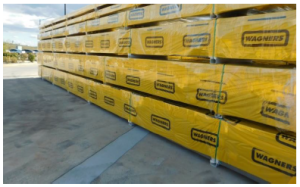
Figure 8 – Wrapped shipment ready for transport
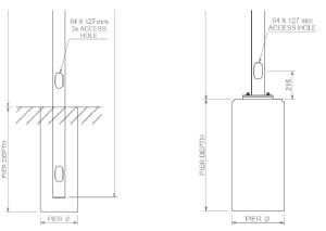
a) Direct burial b) Anchored base
Figure 9 – Light poles installation
Case Study: Qantas Group Pilot Academy:
The successful completion of the previous stages i.e. manufacturing, testing, design and installation resulted in utilising PFRP light poles in several completed projects in Australia and overseas. A good example of that is Qantas Group Pilot Academy in Toowoomba Region, Queensland, Australia where PFRP light poles are installed (Figure 10). The client selected the PFRP light poles over the traditional light poles considering the favourable properties of the former i.e. high durability and maintenance-free. The installed PFRP light poles are performing well structurally/mechanically against the different loading conditions, and aesthetically/physically against the various environmental factors i.e. UV, humidity, etc.
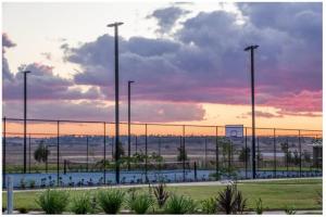
Figure 10 – PFRP light poles at Qantas Group Pilot Academy
Conclusions:
This paper discussed the main parameters of PFRP light poles production at all stages i.e. manufacturing, testing, design and installation. The light poles were manufactured by the pultrusion process with a novel pull winding technique resulting in a unique light pole with relatively high mechanical properties in both the longitudinal and transverse direction as revealed in the material characterisation and large-scale testings. A complete and certified structural design was then developed and the PFRP light poles were installed in various locations. Finally, the transport and installation of PFRP light poles were more efficient compared to traditional light poles given the lightweight of the former.
Acknowledgements:
The authors acknowledge the efforts of James Bourke of Wagner CFT in undertaking the experimental tests. They also acknowledge the contribution of Matthew Gorring Kehoe Myers in the structural design of Wagners CFT composite light poles.
References:
ADVANI, S. & HSIAO, K.-T. 2012. Introduction to composites and manufacturing processes. Manufacturing Techniques for Polymer Matrix Composites (PMCs). Elsevier.
AS/NZS 1170 2002. Structural Design Actions. Standards Australia.
SAKR, M., EL NAGGAR, M. & NEHDI, M. 2005. Interface characteristics and laboratory constructability tests of novel fiber-reinforced polymer/concrete piles. Journal of Composites for Construction, 9, 274-283.
SALIB, S. & ABDEL-SAYED, G. Dynamic behaviour and seismic response of FRP light poles in high seismic zones. Proceedings of 6th International Conference on FRP Composites in Civil Engineering. Rome, Italy, 2012.
WAGNERS CFT 2016. Product Guide. 04 ed.: Wagners.