Jeff Peay (Landscape Architect – AILA), Landscape Architect, Mackay Regional Council
Michael Kemp (BE(Civil)), General Manager, Wagners CFT
Juan Gonzalez (BE(Civil)), Project Engineer, Wagners CFT
INTRODUCTION
The use of composite materials in the construction industry has greatly increased in the 21st century and has gained acceptance as a commercially viable alternative to steel and timber in new civil infrastructure. Applications such as pedestrian boardwalks and footbridges have been found to greatly benefit from their use with reduced maintenance, reduced whole of life costs and enhanced durability, placing them above other traditional materials. Offering a combination of high strength, low weight and long service life, composite materials are increasingly being sought by clients from both government and industry to satisfy the demands for infrastructure solutions. Wagners has pioneered the application of composite materials and have completed numerous projects in Australia as well as exported products to the United States, Russia, Malaysia and Brazil.
The Bluewater Trail project in Mackay is one of many projects utilising fibre composite materials in Australia, however it is the first project of its kind in Australia to utilise driven fibre composite piles. This paper outlines the design of the structure and subsequent analysis of the substructure.
PROJECT BACKGROUND
The Mackay Regional Council area is one of the fastest growing regions in regional Australia and is centrally located between Cairns and Brisbane in Queensland. Mackay’s coastal location, mild climate, proximity to The Great Barrier Reef and the unique Pioneer River environment offers diverse recreational opportunities to residents and visitors alike. The Bluewater Trail in Mackay is an ongoing part of the development of the regions recreational opportunities and when completed will provide a 21 km ring of mixed-use integrated trail system linking the city centre, several environmental and public open spaces and the city’s beaches.
The latest stage of the Bluewater Trail is known as the Environmental Park and includes over 1.8 km’s of shared pathway and boardwalk that meander through the Pioneer River flood plain and link up with existing sections of the Bluewater Trail. Over 800 metres of boardwalk were required through this environmentally sensitive flood plain area containing several mangrove species and other unique flora and fauna associated with the Pioneer River.
Mackay Regional Council’s vision and commitment to sustainable development practices required that it research alternative materials to timber for the boardwalk construction. This material or product would need to be relatively maintenance free, cost effective, and an aesthetically appropriate alternative to timber given its location in the Environmental Park. The Pioneer River also experiences regular level fluctuations due to tidal and flooding events. For this reason, the boardwalk sections would need to be constructed of noncorrosive materials to withstand saltwater inundation and exposure to Acid Sulphate Soils as well as structurally capable of withstanding Q100 flood level events. These challenging local conditions and the complexity of the brief required an innovative structural solution that provided zero maintenance and minimised disturbance to the area during construction and for the balance of its design life. A variety of options were researched and it was determined that the Wagners composite model would provide the best outcome for the boardwalk sections given the local conditions and project requirements.
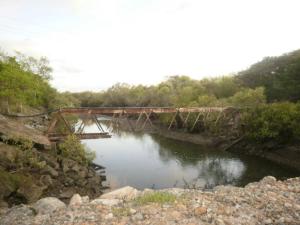
Figure 1 – Extremely corroded crossing due to high salinity waters.
BOARDWALK CONCEPT AND LANDSCAPE DESIGN
The boardwalk along with the associated concrete pathways direct visitors through a series of natural environments and viewing areas including several rest areas that provide shade, seating and interpretive opportunities. The boardwalk sections were intended to provide controlled access to a unique section of the Pioneer River environment while minimizing the impact to the natural landscape. Years of degradation due to off-road vehicle use and illegal dumping had a negative impact on the site and native vegetation. The boardwalk was designed to meander through several different zones within the river corridor and assist in keeping visitors on a limited route through the site that will allow for revegetation of native species to occur and erosion to be reduced.
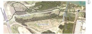
Figure 2 (a) – Boardwalk General Arrangement (Satellite)
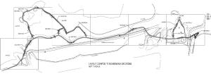
Figure 2 (b) – Boardwalk Layout (Contour)
STRUCTURAL DESIGN
Mackay Regional Council (MRC) engaged Wagners CFT to provide a concept design for the elevated boardwalk structure sections based on MRC’s landscaping concept. Wagners CFT opted for a design which utilised FRP driven piles and superstructure, recycled plastic decking and Grade 316 stainless steel connections and toprail. The use of these materials provided MRC with an environmentally sustainable and economical solution which achieved the desired project outcomes.
The use of driven piles was necessary (as opposed to high level footings) as the presence of acid-sulphate soils made any ground disturbance unattractive, and the very high flood forces demanded a ‘high’ capacity footing.
Material Selection
Glass Fibre Composite
Glass fibre composite or fibre reinforced polymer (FRP) materials offer high strength, low weight, and long service lives as they are not prone to corrosion, rot or shrinkage as other materials more traditionally used by civil industry. The high salinity of the regions waters and frequently expected inundation meant that traditional framing materials, such as galvanised steel and timber, were not viable options. By using composite materials, MRC eliminated their ongoing maintenance costs and therefore significantly reduced the whole of life costs for the project. A life cycle cost analysis performed by another local council found that the use of fibre composites for boardwalk superstructures can effectively half the 50 year whole of life costs when compared to hardwood timber, and lower costs by almost 50% when compared to steel.
The FRP materials used were manufactured using the pultrusion process creating sections that are geometrically similar to rolled-steel rectangular hollow sections (RHS). This process combines a vinyl ester resin with an ECR-type (corrosion resistant) glass, resulting in high-strength structural components that are not prone to rot, corrosion or shrinkage. An additional polyester external veil and 2-pack paint is added to further increase its UV resistance and durability.
Recycled Plastic Decking
Specifying a non-corrosive plastic decking in combination with FRP structural members is a very effective method of reducing maintenance costs associated with boardwalks. Replas Enduropank was specified for use in this project and is made of recycled plastic. It will not rot under damp conditions, be attacked by insects, warp, shrink, swell or splinter. It does not need to be routinely oiled like traditional timber decking which creates high maintenance savings.
316 Grade Stainless Steel
The connections and handrail system utilised 316 Grade Stainless Steel to ensure maximum durability in the highly corrosive conditions. 316 Grade, otherwise known as marine grade, has better overall resistance to corrosion than the more common 304 Grade, especially in chloride environments.
Design Criteria and Codes
The project was an elevated boardwalk and as such was designed to AS2156 – Walking Tracks and classified as a Walking Track Structure – Class 3. Provisions for cyclists were allowed for and AUSTROADS: Guide to Traffic Engineering Practice Part 14 – Bicycles served as a reference for handrail and ramp requirements. All composite elements were designed to the Structural Design of Polymer Composites – EUROCOMP Design Code and Handbook with load combinations and wind loading obtained from AS1170 – Structural Design actions and water loads obtained from levels and velocities provided by council.
The superstructure was a composite framing system which combined continuously supported joists with simply supported bearers to optimise spans and minimise environmental disturbance. The maximum longitudinal span where joists were continuously supported was 4.6m and in instances where joists were simply supported was 4.0m. Composite handrails and stainless steel top rails were used in regions where fall heights were greater than 0.9m, in accordance with AS2156.
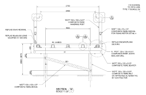
Figure 3 – Typical Boardwalk Cross Section
The substructure was a composite piles system driven in varying geotechnical conditions, from uncontrolled fill to alluvial soils. Driven piles were chosen due to the presence of Acid Sulphate Soils across the site which would require liming if boring or excavation was to be performed.
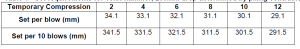
The design of the driven pile system required preliminary testing to determine design pile lengths. The suitability of using existing dynamic formula for conventional driven piles was explored by performing preliminary static pile testing on composite piles driven around the site. The piles were driven to a set calculated from the Hiley Formula for the required resistance with a minimum of 2m embedment required for uplift. After the completion of preliminary static load tests, it was found that an average 2.5m embedment was required to achieve ultimate pile loads, requiring piles lengths between 4-6m. If greater lengths were required, a splice, similar to what is used for timber construction, was designed to allow for continued driving.
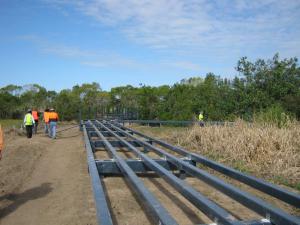
Figure 4 – Bluewater Environmental Trail under Construction
ANALYSIS
As this was the first project to utilise driven FRP piles, significant analysis and testing of the piling system was undertaken to ensure its structural adequacy.
Pile Testing Program
The following program was followed to form the acceptance of the composite pile system:
1. 100% of all piles will have their capacity assessed by using an approved empirical energy equation (in this case the Modified Hiley Formula) for the adopted hammer and drop height to determine an acceptable set. The SWL was determined by the load case (G+Q) and the low risk of injury to occupants in the event of a failure as well as the nature of the structure allowed the factor of safety to be reduced to 2.
Equation 1 – Modified Hiley Formula
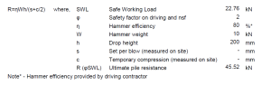
Table 1 – Set requirements for 10kN hammer, 200mm drop determined by piling contractor
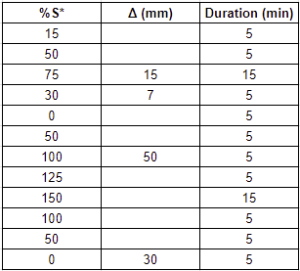
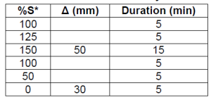
2. 5% (20) of piles selected at random from the driving line by the certifying engineer shall be tested using suitability criteria (a modified version of the incremental sustained load test) as outlined below.
Table 2 – Suitability Criteria Test Program
Note:
- Δ (mm) is the maximum allowable displacement
- Duration is the time held at %S* as a constant load
- S* is the design action effect corresponding to limit state design (In this case 1.2G + 1.5Q =30.4kN)
3. 5% (20) of piles selected at random from the driving line by Wagners CFT shall be tested using modified suitability criteria as part of its quality assurance.
Table 3 – Modified Suitability Criteria Test Program
Note:
- Δ (mm) is the maximum allowable displacement
- Duration is the time held at %S* as a constant load
4. 1% (4) of piles selected at random locations offset from the driving line by the certifying engineer shall be tested using proving criteria based on the standard testing program given in AS2159 Tables 8.1 & 8.2
Figure 5 – Static load testing in progress
5. 1% (4) of piles selected at random by the certifying engineer shall be tested dynamically
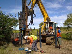
Figure 6 – Measuring the set while performing PDA tests
Initial Observations & Analysis
After 4 days of initial piling and testing, a review was performed and the following findings and recommendations were made:
- Due to very poor ground conditions in section 1 of the project, many of the piles did not achieve the required set when driven to design levels and had to be spliced. Splices were quickly performed on site and did not delay the pile driving rig. Overall driveability was excellent and progressed quickly as the piles were easily managed by a team of 2 workers due to their lightweight nature
- Initial suitability criteria testing found that the piles were capable of withstanding a load 150% of S* at sets much greater than given by the Hiley Formula
- Damage to the top of the pile due to the hammer impact was virtually non-existent and examinations of the pile integrity after driving found no damage to the bottom of the pile
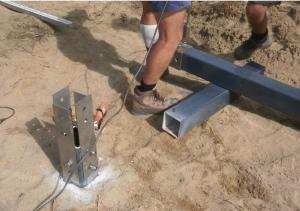
Figure 7 – Pile splice being prepared on site
Testing Analysis
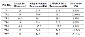
To check the accuracy of the calculated ultimate resistance from the Hiley formula, dynamic pile testing was performed on test piles in 7 main regions around the site. The set per blow was used to calculate a resistance which was then compared to CAPWAP analysis as seen in Table 4. The Hiley formula was accurate in predicting the resistance and tended to overestimate the capacity of the pile when compared to the CAPWAP analysis. This confirmed the suitability of using existing dynamic formula for composite pile systems.
Table 4 – Hiley Predicted Capacity vs CAPWAP Capacity
In order to correlate the CAPWAP analysis and suitability criteria test results, the static analysis displacements were compared to the recorded displacements at 45.52kN (150%S*) which can be seen in Table 5 and Figure 8.
Table 5 – CAPWAP analysis vs Suitability Criteria results at 45.52kN
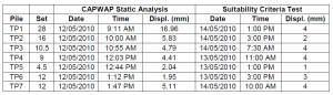
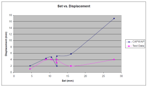
Figure 8 – Relationship between CAPWAP analysis & Test Data
The predicted displacements follow a similar trend for the smaller sets and become more inaccurate as the set increases. This discrepancy can be attributed to the following reasons:
- The CAPWAP analysis predicts the static behaviour of the pile at that particular moment in time called the mobilised capacity. The mobilised pile capacity is directly related to the movement of the pile during testing. Since TP1 and TP2 had high sets of 28mm and 16mm respectively, the CAPWAP analysis will reflect these high sets by predicting high static displacements. As the test was completed directly after driving, this mobilised pile capacity can be very different from the long term ultimate pile capacity
- Due to the nature of soils and the changes in pore pressure distribution over time, the resistance of the pile can dramatically change due to soil set-up or relaxing. TP1 and TP2 had the longest time between tests (51 hours +) and have the largest discrepancies which can be attributed to significant soil set-up. As all the piles have similar static load test results (3mm difference in range as can be seen in Figure 8) it is predicted that the CAPWAP analysis will return similar values if performed directly after completion of the static test
In total, 410 piles were driven in less than two weeks with all obtaining the required set. The predicted total resistances were much higher than the working load with a minimum factor of safety of 2. This can give confidence into both the testing methods used and the design process followed. The piles tested according to the proving criteria were well within the stipulated acceptance criteria given in AS2159 Table 8.2 and therefore deemed acceptable.
CONCLUSION
This paper looks at the design and analysis of an innovative, all composite project which featured a driven FRP pile system unlike any other project of its kind in Australia. The structural adequacy and practicality of utilising driven FRP piles was proven by an extensive testing regime and paves the way for future projects. Construction was carried out by Abergeldie Complex Infrastructure and began at the end of April 2010. The installation works took approximately 2 months to complete and was officially opened to the public on schedule by the end of June 2010. By achieving the project objectives, the elevated boardwalk structure was met with wide public praise and now serves as an essential link to Mackay’s vast green spaces.
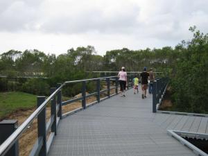
Figure 9 – Members of the public enjoying the boardwalk