Ali Mohammed (1), Michael Kemp (1), Rohan McElroy (2), and Brett Jennings (3)
1 Wagners CFT, Toowoomba Qld Australia
2 icubed consulting, Brisbane Qld Australia
3 Wallbridge Gilbert Aztec, Adelaid SA Australia
* Ali Mohammed. Email: ali.mohammed@wagner.com.au
ABSTRACT:
The utilisation of glass fibre reinforced polymer (GFRP) materials in civil/structural applications have exponentially increased in the last few years. The increased use of GFRP was in both forms as in new structures, and repairing/retrofitting existing ones. The reason behind using FRP materials in the vast majority of recent structural repair/retrofitting projects is the unique and favoured characteristics in terms of strength, weight, durability and corrosion resistance. These superior properties make GFRP materials very versatile and always attract new areas of applications. A good example of that is GFRP bridge decks as they are a perfect replacement for deteriorated old decking system without increasing the dead weight of the structures which eliminate the need for any foundation retrofitting work.
The Birkenhead bascule bridge is an excellent case study for GFRP bridge decks as the old timber deck was being replaced twice a year for a certain period of time until it was been swapped with innovative GFRP BridgeDeck manufactured by Wagners. This paper describes the case study of Birkenhead bridge deck replacement and discusses the various stages of work involved in this project to make it achievable. The various work stages involve manufacturing processes, fabrication and assembly, experimental static and cyclic tests, proof loads, FEA analysis, detailed engineering design and installation. Finally, it highlights the structural integrity of the utilised BridgeDeck in such applications.
KEYWORDS: pultrusion, FRP composites, bridge decks, deterioration, bridge repair, Birkenhead bridge.
1 Introduction
Maintaining the existing road bridges operational, especially those located in harsh marine environments is a major challenge for many transport authorities and asset owners around the world [1]. The constant weathering and environmental distress can have drastic effects on the durability and functionality of conventional structures i.e. reinforced concrete (RC) decks due to the corrosion of steel rebars as chloride and moisture ingress through surface cracks [2]. In Australia, the risk of bridge deterioration is increasing where most of the aged timber bridges are structurally deficient. Around 40% of the bridges in the US can be classified as structurally defective due to steel corrosion [3]. In Canada, almost half of the bridges constructed 40 years ago are experiencing corrosion damage, mainly due to de-icing salts [3]. These concerns urged the necessity to develop innovative, cost effective and durable repair methods.
In the past two decades, glass fibre reinforced polymer (GFRP) materials have become very popular and versatile due to their superior characteristics compared to traditional materials i.e. concrete, steel and timber. The favourable properties of GFRP materials such as high strength, light-weight and corrosion resistance, have made it the material choice for structures in aggressive environments. A good example of that is pultruded GFRP bridge decks as it is one of the most promising GFRP products for composites in infrastructure. Composite GFRP bridge decks offer a very durable and cost-effective solution to deteriorated decks, and a good alternative for new construction. The reason behind that is attributed to the inherent properties of the bridge decks’ constituent materials which allow for rapid installation, zero maintenance with minimal disturbance to the daily commute and goods transport. The rapid installation and minimal traffic disturbance provide better economical and sustainable impacts compared to traditional repairs as there will be less carbon emission during the construction work in the case of using GFRP deck systems [4].
Generally, pultruded GFRP deck systems can be fabricated by assembling several pultruded FRP hollow sections adhesively bonded together forming the bride deck unit. The fabricated composite bridge deck is typically oriented along the direction of the main fibres of the constituent members and transversely with respect to the traffic direction. There are several studies have reviewed and evaluated the structural performance of GFRP bridge decks under flexural loads [5, 6]. The studies showed that the structural performance of the GFRP bridge decks is highly dependent on the sectional and mechanical properties of pultruded members.
Recently, a novel GFRP bridge deck has been developed by Wagners Composite Fibre Technologies (WCFT) where several pultruded square hollow sections are bonded together. The bonded members act compositely forming one integral element at custom length and width. This paper presents and explains the fabrication process of the individual GFRP hollow members, and the whole assembly of the GFRP bridge deck. It also describes the large-scale flexural and fatigue testing procedures and discusses the experimental results of the deck testing. Finite Element Model (FEM) has been developed and validated with the experimental work. Finally, the successful completion of this study resulted in utilising the developed bridge deck in many actual road bridge repair projects. A case study of that is Birkenhead bridge project in Adelaide, South Australia where the advantages of using FRP decks during the installation and in-service stage are highlighted.
2 GFRP BridgeDeck
2.1 Manufacturing Process
The individual pultruded FRP hollow sections are manufactured by the pultrusion process where glass fibres are pulled through a heated die whilst it is being impregnated with a specific resin mix through injection as depicted in Figure 1. The wetted-out material is pulled over a heated stainless-steel mandrel that ensures it holds its shape during the curing process. The heaters that are located in the die initiate the exothermic reaction to cure the resin and solidify raw materials into one integral section. An automatic cutting saw is located at the end of the pultrusion line programmed to cut the finished products at pre-defined lengths. Unique pull winders are integrated with the pultrusion line allowing novel fibre layup which involves several layers of unidirectional fibres (UD) and wound fibres (WD). The UD/WD ratio and the off-axis angle of the wound fibres can be tailored depending on the desired mechanical properties of the final product, i.e. whether higher strength is required in the longitudinal direction or along the transverse/hoop direction. Therefore, the individual FRP members of the deck are manufactured with UD/WD ratio of 80/20 with a WD angle of 50° off the longitudinal axis achieving high longitudinal strength and stiffness, with sufficiently high transverse strength to manage the exerted multi-axial stresses.
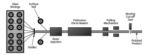
Figure 1: Schematic diagram of the pultrusion process
2.2 Fabrication and Assembly
The manufactured FRP hollow sections are bonded together forming the whole deck unit. The bonding process starts with sanding the surfaces to be bonded by 0.5mm to remove the top resin layer and polyester veil to assure the bonding is occurring between the outer longitudinal/structural fibres. Then, two parts of toughened epoxy resin are used as an adhesive where it is applied on the sanded surfaces and clamped together under constant pressure (Figure 2: GFRP sections bonding jigs) with a thermal cure cycle. Moreover, the top and bottom surface of the fabricated FRP deck is hand laminated with one layer of 900 GSM Weft Triax Mat and epoxy resin to increase the integrity of the FRP decking. Finally, a shear key layer can be placed onto the top surface to provide better interlocking with the road pavement layer. A schematic sketch of the GFRP decking is presented in Figure 3.
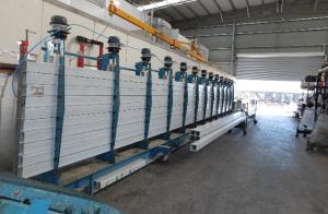
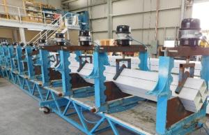
Figure 2 – GFRP sections bonding jigs
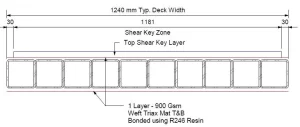
Figure 3 – Schematic diagram of the GFRP decking
3 Experimental Program
3.1 Test Samples
Two decking units were fabricated by bonding 8 GFRP sections (125 SHS) at 3700mm long. The top and bottom surfaces of the GFRP decking were hand-laminated with an additional layer of glass fibre mat (900 GSM Weft Triax Mat) using epoxy resin. The shear key layer was not included in the test samples as its structural contribution is not considered in the design. Prior to each test, the test sample was inspected as per Wagners QA procedures to ensure no manufacturing defects were apparent. Finally, a distributor beam (125 SHS) was used underneath the decking units to prevent the differential deflection and lifting of the tested panels as shown in Figure 4.
3.2 Test Setup
Figure 4 depicts the test setup and instrumentation of this study. The GFRP decks were supported with steel supports over two clear spans of 1850mm. The load was applied at the edge-midspan of the deck, simulating the worst-case scenario. The load was applied using hydraulic jack with a steel plate of 10mm thickness at the loading point complete with a sheet of neoprene rubber to ensure uniform distribution of the applied load across the cross-section, and to minimise the edge effect of the steel plate. The magnitude of the applied load was measured with 500kN capacity load cell, whereas the corresponding deformation was measured with a linear string potentiometer installed directly beneath the loading plate on the underside of the distributor beam (denoted as SP1 on Figure 4). The test specimens were loaded in proof test and cyclic test before loading it to failure as explained in the following sections.
3.2 Proof Test Load
The test loads for this project were determined based on the vehicle wheel loads from AS5100 – Bridge Design Code and Austroads ’92 – Bridge Design Code. The reason for using the ’92 Bridge Code was to include a T44 (W7) design vehicle in the analysis as a significant number of existing bridges in the Australian road network have been designed for this vehicle in the past. In addition to the above, AT22 Crane wheel load was also included in the testing program. It should be noted that from here out, the T44 load will refer to Austroad ‘92’s W7 wheel load and SM1600 will refer to AS5100.2’s W80 wheel load. The test sample was proof loaded for AT22 and SM1600 only and it was assumed to be satisfactory for T44 loading if the test passed the SM1600 load requirement. The justification of this assumption is that both T44 and SM1600 have very comparable design loads and loaded area dimensions. All test loads have considered the ultimate limit state and dynamic load factors as per AS5100.2, and a testing variability factor as per AS/NZS1170.0. A summary of the test loads and calculations is detailed in Error! Reference source not found.
3.2 Cyclic Load
Cyclic testing for two million cycles was undertaken to investigate the fatigue performance of the GFRP deck under continuous cyclic loads following the same test setup used in the flexural test. To confirm structural integrity throughout the fatigue test, a series of spike testing was undertaken every 100,000 cycles. The load used during the cyclic testing and spike testing is as follows:
Fatigue Loading = 10 – 100kN
Spike Load = 150kN
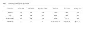
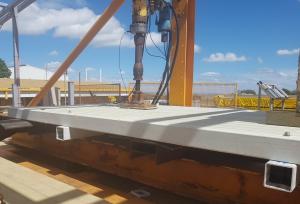
Figure 4 – Test set up
4 Analysis of Results
4.1 AT22 Proof Load
The calculated test load for AT22 loading case is 140kN as presented in Table 1. The test sample was loaded up to 145.7kN, which is 4% higher than the factored ultimate test load. The applied load was held for more than 15 minutes, then unloaded. No noise was heard during loading, neither any sign of failure was observed in the deck as the test samples deformed linearly with the applied load as shown in Figure 5. Therefore, the test sample was deemed to pass the structural proof testing.
4.2 T44 and SM1600 PROOF LOAD
As discussed previously, the T44 load case was not specifically tested and was considered to be acceptable if the deck was found to be structurally adequate for SM1600 loading. Therefore, the sample was loaded directly to the highest load case i.e. SM1600 with 246.6kN ultimate load. This load was held for more than 15 minutes with no trace of any signs of failure. Hence, SM1600 load case, and therefore T44, deemed to pass the structural proof testing.
4.3 Ultimate Load
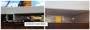
After the GFRP deck passed the structural proof testing of all load cases, it was then loaded up to failure to determine its ultimate capacity. As shown in Figure 5: Load – deflection curves the load was increased linearly with the deformation until the sample failed ultimately at 378.2kN. This is 53% higher than the ultimate testing loading case. The failure mode was found to be the flexural buckling of the distributor beam beneath the applied load where the two panels joined (Figure 6). The remainder of the panel structure was inspected, and no damage or signs of failure were apparent.
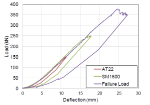
Figure 5 : Load – deflection curves
4.4 Cyclic Loading
The GFRP deck was tested for two million cycles (10-100kN) with a spike load of 150kN every 100,000 cycles as shown in Figure 7 where the spike load results were grouped and analysed against the observed displacement. It is evident from Figure 7 that the slope generally remains consistent over the 2,000,000 cycles. There were no major outliers or differences in the graphed curves apparent. Moreover, there was no structural cracks or damage were found in the GFRP deck. This proves that the structural performance of the tested sample (BridgeDeck 125) section remains constant after the significantly high number of repetitive cyclic loadings.
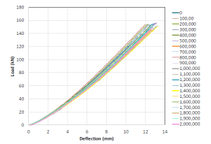
Figure 7 : Spikes Loads – fatigue test
4.4 Finite Element Analysis
A Finite Element Model (FEM) was developed using Strand7 software and was validated with experimental work where the FEM accurately captured the behaviour of the GFRP deck. A snapshot of the developed model for the AT22 load is presented in Figure 8. It can be shown that test load deflections curves correspond very well with the deflections obtained from FEA of the GFRP deck units with the distributor beams modelled with an acceptable level of variation. The developed FEM model will be a very useful tool for future parametric study and/or in the design validation of future projects.
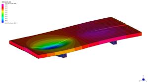
Figure 8 : FEM model showing testing deflection (exaggerated)
5 STRUCTURAL DESIGN SUMMARY
The design of the FRP decking structure for Birkenhead Bridge was undertaken to Austroads ’92 design criteria to match the existing structure’s design intent. This included the standard T44 design vehicle along with the W7 wheel load. The W7 wheel loading governed the design of the decking panels for this project.
In addition to the vehicle wheel loading requirements, the deck was also designed to withstand various other loading conditions including vertical and lateral wind loading, seismic loading, thermal loads and gradients, vehicle braking forces and minimum lateral restraint loads.
The deck replacement consisted of 24x WCFT BridgeDeck 125 sections laid across the length and width of the existing deck. The FRP deck system sat atop of the existing structural steel girder beams from the original bridge. The existing structure had a requirement for the proposed decking system to be light-weight in nature and below a maximum allowable weight limit. In this instance, the panel system was well below the required maximum weight, providing a promising solution for the longevity of the bridge and less load on the mechanical bascule.
The BridgeDeck 125 panels were fixed to the existing steel girders by using bolted PET insert assemblies. A bolt group was installed at each FRP deck and existing steel girder crossing to ensure adequate tiedown and shear transfer. The FRP deck system also sat atop of an industry standard bridge rated elastomeric rubber bearing pad. The bearing pads help to protect the FRP sections from high concentrated point loads from bearing on the steel girders below.
Thermal loading was undertaken in accordance with Austroad’s ’92 and applied to a simplified deck model in SPACEGASS to assess deck expansion and contraction requirements. The required thermal movement potential was accounted for in the detailing of the decking system and connections.
The ultimate and serviceability design verification of the FRP decking was undertaken using the testing methodology described above in accordance with AS/NZS1170.0 Appendix B. In addition to this, limit state design checks were undertaken using previously determined member capacities for the sections. PET inserts were utilised at bolt locations to provide crushing and shear resistance from design vehicle braking loads which governed the lateral structure design.
The basis of the FRP design of these elements has been undertaken by WCFT and Icubed previously to two international FRP codes: Eurocomp Design Code and Handbook by John L. Clarke and ASCE Pre-Standard for FRP Structures. These two documents provide methods to assess member design capacities such as bending, shear and axial loads, but also address fatigue and creep performance over the design life of the structure. Fatigue cycle calculations were carried out in accordance with Austroads ’92 requirements for T44 vehicles and W7 wheel loading and formed the basis for the fatigue testing program. The creep performance of the panel system provided positive results due to its inherent light-weight nature and strength. The fatigue and creep capacity of the material was calculated using ASCE Pre-standard.
The decking distributor beam was assessed for load carrying capacity and its intended purpose is to minimise differential deflections that may occur between edge panel loading as wheel loads traverse from one panel to the next. Particular attention was paid to relieving stresses around the panel joints for this purpose.
In addition to the static FEM, a transient heat analysis model was also set up to investigate the thermal effects of heavier flexible pavement sealing options for this project and others. The transient heat analysis was undertaken using Strand7 with the purpose of investigating the potential heat transfer from a hot-mix application to the underlying FRP materials. The positive results from the testing program described above provided confidence in the deck system performance. The information retrieved from the testing program was also used to assess stresses, strains and deflections in the Finite Element Modelling process which flowed through to design outcomes on this project and others.
5 Case Study – Birkenhead Bridge
The Birkenhead Bridge, in Port Adelaide, South Australia carries approximately 15,000 vehicles a day across the Port River. The bridge was constructed in 1940 and comprises nine (9) spans totalling approximately 260m in length, with an average carriageway width of 15.8m (Figure 9). The spans include eight normal spans and a central double-leaf bascule span. The Bridge is listed on the South Australian State Heritage Register due to the significance of the bascule span which opens to allow the passage of vessels beneath.
The timber running surface of the bascule span had deteriorated and required regular maintenance where defective or worn asphalt coated timber tiles were patched or replaced approximately 3-4 times per year. Wallbridge Gilbert Aztec (WGA) was engaged by the South Australian Department for Infrastructure and Transport (DIT) to investigate and design an alternative bridge deck system for the bascule span. The objectives of the works were to improve safety for the users of the structure, extend the life of the bridge asset and to provide ongoing safe access for water transports.
Part of WGA’s scope was to undertake an options study to assess potential structural systems for the deck replacement. Key criteria considered were deck weight, thickness, constructability, durability and cost. Weight was of particular importance given the limitations of the existing mechanical and electrical plant for the bascule span. In conjunction with DIT, the structural system selected for the deck replacement was Wagners 125 WCFT decking system.
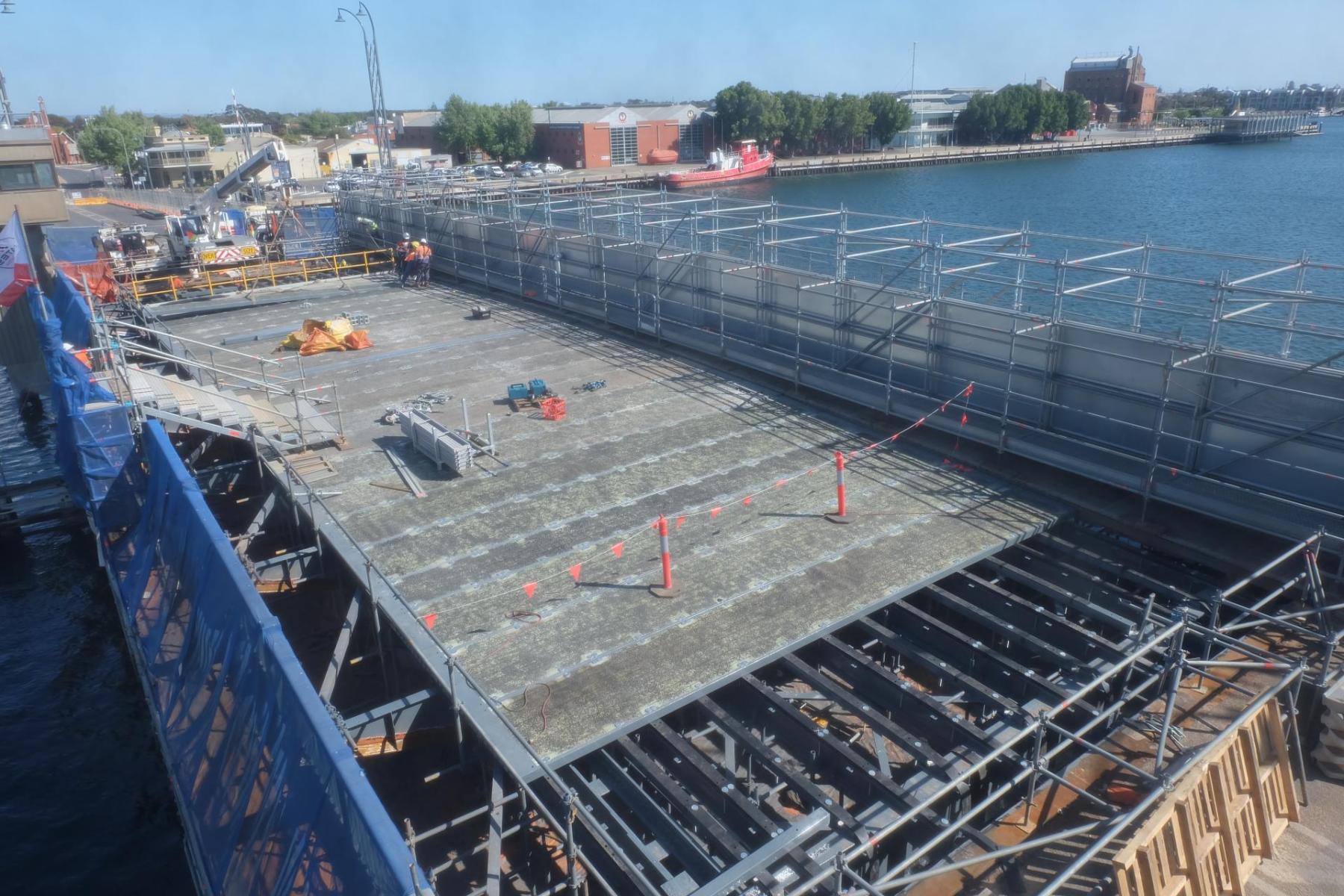
The new decking was installed on top of the existing steelwork (Figure 10) with nominal HDPE packers, where required, to match the existing roadway surface. A minimal thickness deck wearing surface was then installed on the new WCFT decking. In order to confirm the satisfactory performance of the deck wearing surface during the bascule opening in summer conditions, Wagners constructed a test panel including the deck wearing surface, heated it to 60oC degrees in an oven whilst positioned vertically (at 90 degrees), and then performed shear tests to simulate Austroads braking loads.
The works were successfully completed and the bridge was open to traffic (Figure 11) in late 2020 with the construction performed by McMahon Services.
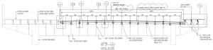
Figure 9 : Typical section of Birkenhead Bridge

 Figure 10 : Installation of Wagners FRP BridgeDeck 125 and Figure 11 : Birkenhead Bridge with Wagners FRP BridgeDeck 125
5 Conclusions
This paper presented the overall heritage repair process of Birkenhead Bridge using the innovative GFRP bridge deck units comprising several FRP hollow sections bonded together. It also discussed the experimental results of the full-scale flexural and fatigue test on the GFRP decking unit. Moreover, the developed finite element model was validated with the experimental results which offer a useful tool for further parametric study or in designing future projects. The successful completion of this study/project resulted in utilizing the novel GFRP deck in several subsequent projects.
Acknowledgments
The authors acknowledge the efforts of and James Bourke and Matt Weise of Wagner CFT in the experimental work of this study.
References
1. Val, D.V., M.G. Stewart, and R.E. Melchers, Effect of reinforcement corrosion on reliability of highway bridges. Engineering structures, 1998. 20(11): p. 1010-1019.
2. Li, X., et al., Cyclic behavior of damaged reinforced concrete columns repaired with high performance fibre-reinforced cementitious composite. Engineering Structures, 2017. 136: p.26-35.
3. Nkurunziza, G., et al., Durability of GFRP bars: A critical review of the literature. Progress instructural engineering and materials, 2005. 7(4): p. 194-209.
4. Kumar, P., K. Chandrashekhara, and A. Nanni, Structural performance of a FRP bridge deck. Construction and Building Materials, 2004. 18(1): p. 35-47.
5. Xin, H., et al., Analytical and experimental evaluation of flexural behavior of FRP pultruded composite profiles for bridge deck structural design. Construction and Building Materials, 2017. 150: p. 123-149.
6. Alampalli, S., J. O’Connor, and A.P. Yannotti, Fiber reinforced polymer composites for the superstructure of a short-span rural bridge. Composite structures, 2002. 58(1): p. 21-27.